
Stubborn triangles

a mauerwerkvorsprung problem in the 21st century
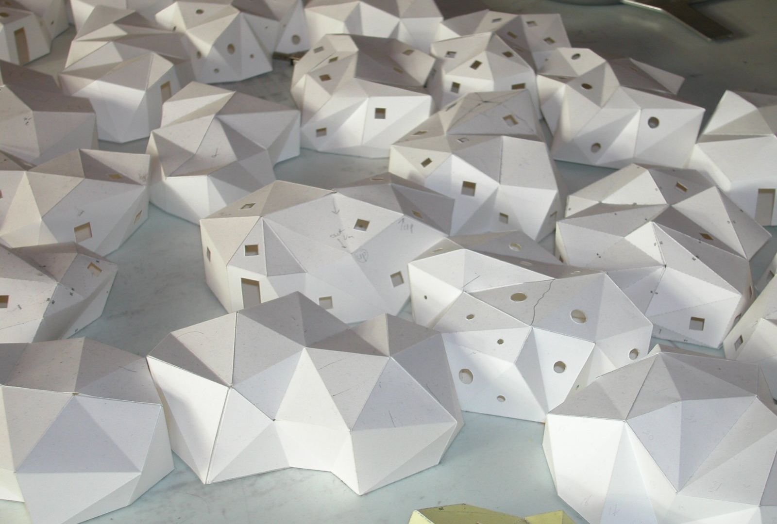
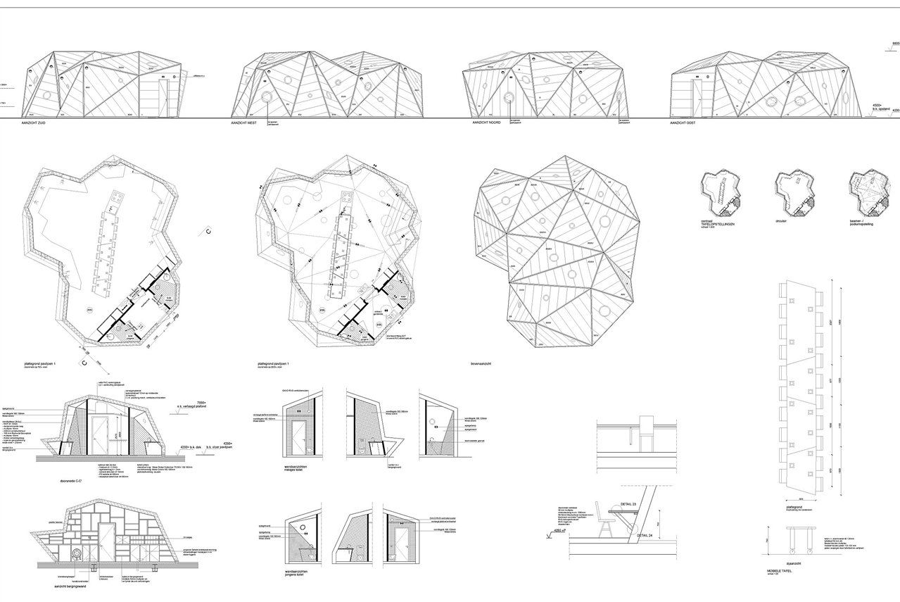
In 2007, Jasper de Haan architects was commissioned to design a new out-of-school care centre on top of an existing day-care centre, since there was no more space on the ground, with two groups of 20 children each. Since 4 m2 of outdoor play space per child was needed in addition to the 3.5 m2 per child internally, the obvious solution was to create a new deck on the roof of the existing building that could serve as a playground. On that deck two pavilions of around 100 m2 each. Very much against our habit, we designed these pavilions as irregular crystalline 'Mario Merz'-like igloos to contrast with the orthogonal 1970s schoolhouse and the horizontal new deck.

We felt that these irregular volumes constructed from triangles should be self-supporting. This because the examples where this kind of design is just a backdrop that has to be kept upright with a lot of invisible propping are becoming too numerous. With the help of designer Paul Lagendijk of Aronsohn Constructies and the Japanese program Pepakura, which allows you to quickly print construction sheets of 3D models from SketchUp, for instance, we were able to determine the shape of the pavilions very precisely. Such that they fitted on the deck, articulated the urban planning situation, had enough free interesting m2 for twenty children, would not collapse and also met our aesthetic requirements. Getting our theoretical computer model with thickness zero to be sufficiently stiff and strong did not prove easy. In particular, second, third and more, order effects sometimes turned out to have disastrous effects on the structure where you did not expect them. But thanks to a fantastic trial-and-error collaboration with the constructor, we had everything under control in the end.

Exploded galaxy
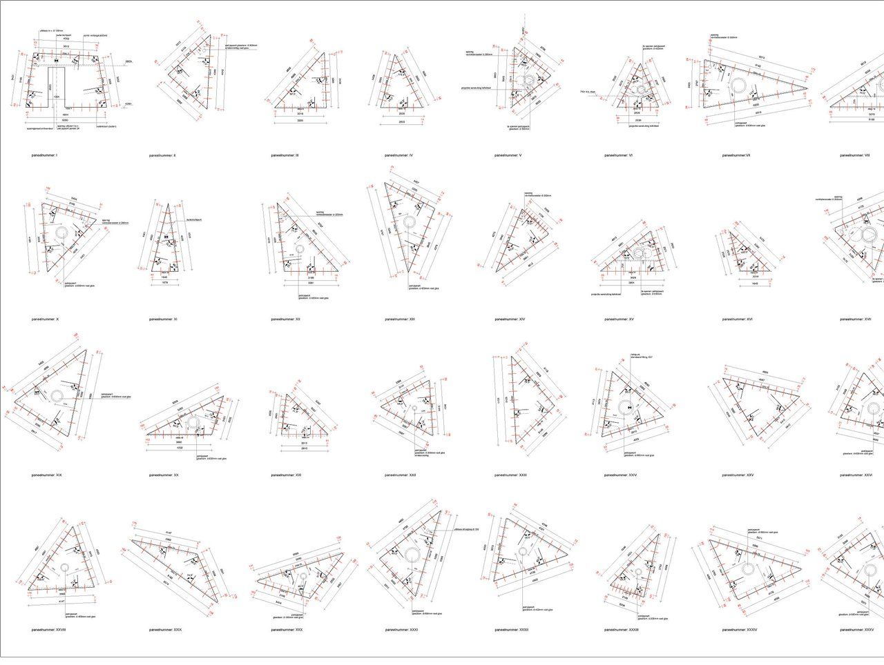
While making the specification drawings for the pavilions seemed like a lot of work to us, it was essentially a piece of cake. A simple editing of our thickness zero model with what is called in AutoCad Offset should have sufficed to then draw out all 36 panels one by one in 2D, so that the carpentry factory could make simple inexpensive timber frame construction panels from them. Great was our surprise when that turned out to be not so simple at all. When we had given the model a thickness, the vertices turned out to behave like an exploded galaxy instead of the neat pyramids with three to eight faces.

Quite apart from the formal and structural aspects, this was especially worrisome because the original vertex no longer existed. It had dissolved into a cloud of points with a diameter of sometimes as much as forty centimetres. And that while during its design, it had emerged that moving a vertex over just thirty centimetres sometimes meant the difference between collapsing or not. So we had a big problem. We didn't understand what was happening, couldn't draw it in 2D, and it was questionable whether our pavilions would remain standing.
The world of parametric geometries
Fortunately, the project was just at a standstill due to objections from our neighbours in an Article 19 and we met Axel Kilian, co-author of the book Architectural Geometry and at that time just employed at TUD. He was able to tell us that our problem had been a classic in his field for a year and introduced us to the world of parametric geometries.
The position of the theoretical computer model with thickness zero was chosen in the centre of the structure. Obvious solutions to still give the model thickness were to make, say, only the inside or only the outside knocking. Apart from the fact that we wanted both sides to be correct and closed, this was also not an option because we could then start designing all over again. Otherwise, the building would be too big or too small. Even simple operations, such as offsetting everything to one or two points, turned out to produce too large thickness differences in the surfaces.

We decided to take a more fundamental approach and apply for a research grant from the Incentive Fund. Which we fortunately got.
Cone

Helmut Pottmann published2 in 2006 how to use a cone to make a 'normal' pyramid with four faces offsetable. However, the question was whether this would also apply to pyramids with more faces and to pyramids with an inlet or dent, as we called them. As systematically as possible, we set up a kind of 'periodic table' for pyramids, which showed, among other things, that it is possible to make pyramids with up to eight faces offsetable. It also turned out that the ground plane of offsetable pyramids with an odd number of faces is a plane and that this need not be the case with an even number of faces. It also turned out that pyramids with dents are indeed offsetable, provided the (extended) tangent is tangent to the base circle of the cone. However, the moment the deepest point ven a dent coincides or ends up beyond the top of the cone, it cannot.

After this exercise and its conclusions, the question was how to offset the connected pyramids all together at the same time. This is tricky, as an offset of one plane of one pyramid immediately results in an offset of that same plane in at least two other pyramids. An infinite adjustment of all pyramids over and over again is lurking. But fortunately, it is possible to name some constants in which to vary. Such as: cross-section of the base circle of the cone, height of the cone, angle of the cone. But after countless attempts with different constants and variables and even an ellipse as a constant (an oblique cross-section of a cone, which has the advantage of two foci), we had to conclude that this was a doomed path.

Iteration: in vain
Iteration seemed the only alternative. In other words: using a lot of blunt calculating power to calculate the deviations back to something that would become negligibly small. Axel Kilian, meanwhile, had engaged his very helpful global network, and at one point, there was heavy computation on the shape we had designed in various places around the world.
But these attempts, too, proved futile. Despite all the highly inventive and powerful parametric calculation methods, the surfaces continued to differ too much in thickness or the end faces were too twisted to be made in simple timber frame construction.

Meanwhile, a year had passed, the neighbours' objections had been declared unfounded and the client wanted to put the project out to tender. At that point, we saw no other way out than to 'manually' clean up the tops of the pyramids in the 3D model in such a way that a buildable structure could be created. We knocked down the 3D panels of the model one by one in Rhino and then made them into a 'normal' 2D specifications drawing in Vectorworks.

By now, however, we had become so suspicious of our own work that we decided to test it first in a 1:10 scale model of birch plywood. We made the connections with super magnets that provide the same tensile strength in scale as in reality the wire ends with staple plates. Fortunately, everything turned out to be correct and also to stay in place.


A plug-in for SketchUp?
The tender went smoothly. The pavilions turned out to be hardly more expensive than a 'normal' CSF building. However, the outdoor play deck proved
to be rather pricey. On top of that, bso outdoor play areas could now suddenly be found off site. This removed the need for the deck and pavilions, and the whole project was off the table. The research ran on for a while and the main conclusion is that it is wise to take into account the offsetability of a free, irregular shape from the beginning of the design process. For now, this is best done by having the surfaces tangent to, say, a sphere. In terms of offsetability, these planes should not be triangles, despite the obvious advantages such as stability and simplicity, but rather irregular quadrangles where the vertices lie in one plane or on a circle. But the main recommendation is the same one already drawn in Architectural Geometry, namely that architects are eager for an optimisation routine in which irregular meshes are 'automatically' drawn as offsetable shapes. Perhaps the makers of SketchUp could come up with a plug-in for this at some point.

This article was previously published in the Architect
The full research report as pdf (1.54 MB)
With thanks to:
Paul Lagendijk, Aronsohn constructies raadgevens ingenieurs bv; Axel Kilian, Princeton University; Hanna Läkk; Ralph Doggen; Gerry Bekhuis; Sarah van der Made; Martijn Stellingwerff TU Delft; Van Dik Hout; Henry Burgers; The Rotterdam Architecture Fund